Recovering FIAT Barchetta radio code
Let’s make a long story short… I’ve been the owner of a FIAT Barchetta for a long time. The radio installed in this car is code protected, meaning that if you disconnect the radio from the car (or the battery from the car) the next time you switch the radio on it asks for a code.

When I purchased my Barchetta in 1996 I received a ticket with my code. During the years I probably changed the code to a different one, I don’t remember. The thing is that some years ago, when I had to change the battery of the car, I was not able to find the ticket or remember the code and my radio has been blocked since then.
So I started my investigation and I managed to have my radio working again in a few days. I’ll explain how in the following, giving all the details, but be advised that it’s not something for a total beginner: you’ll need to have some skills in electronics and soldering, and some specific tools that are more usual for a hacker than for an average car owner…
Searching for information
I searched a lot in the Internet to find a solution and this is what I discovered.
- The easiest way is to ask FIAT Service. With a (really not so) small fee they give you the code (or maybe you should send them the radio to be serviced, I don’t know exactly), but I don’t like this option.
- Other sites in the internet promise to send you a code with a smaller fee than FIAT. I don’t like this option too, since they are probably making money with a list of codes stolen from FIAT (or Grundig, that appears to be the original manufacturer of the radio). Also, I cannot understand how they can send me my code if I have changed it in the meanwhile…
Nothing else. I couldn’t find any code generator or service manual that could be useful. No useful information either from the Barchetta forums around the world. That’s why I gave up for a few years…
Recently I did a new search and found some information that gave me a new hope to try and fix it myself.
- I read somewhere that this radio should be the same model as the Grundig WK1704, with just a different faceplate. The service manual was easily downloadable somewhere and it turned out that the information was correct, at least looking at the display and buttons positions on the front.
- I found a code generator named GRUNDIG.EXE in a Polish site that could be related to this radio.
Reading the service manual and preparing the hardware
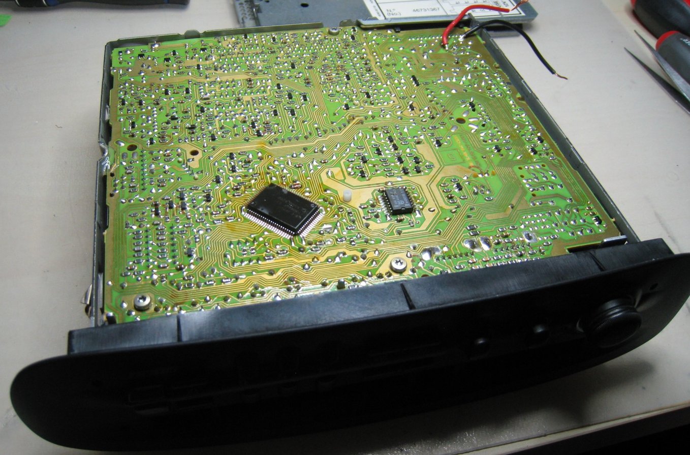
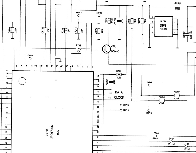
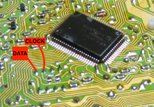
Luckily the service manual seems to fit well the hardware that I have (original radio from my 1996 Barchetta, later ones could be different, I don’t know) and the schematic drawing is available. The important thing is (see page 32 in the manual) that the microprocessor IC701 is connected with a DIP8 memory IC702 through a two-wire interface (clock and data, with pull-up resistors) that seems exactly an IIC bus. This memory could be for example an ST24CXX or equivalent, that could be read and written with an external tool. The schematic names it GR007, but this is probably an internal code. Page 47 shows the position of both processor and memory.
My idea was to remove the memory from the PCB and try to read/write it with an external tool, then resolder it when done. Since the IIC bus is well known and it can be easily “sniffed” on the fly, I decided to try this way first, following the assumption that the radio, at power-on, should read the code from the memory to compare it someway with the one you have to input.
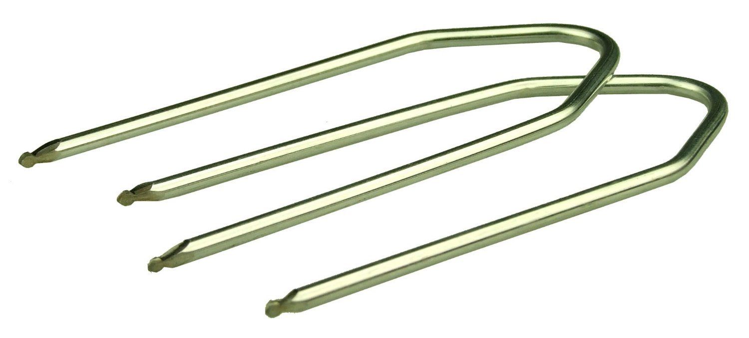
In any case I started removing the radio from the car. Special brackets are needed for this, but I easily found them in ebay and received them in a couple of days. When you pull out the radio from its place you have to disconnect three connectors (power, speakers and antenna), but everything is easy and self-explaining.
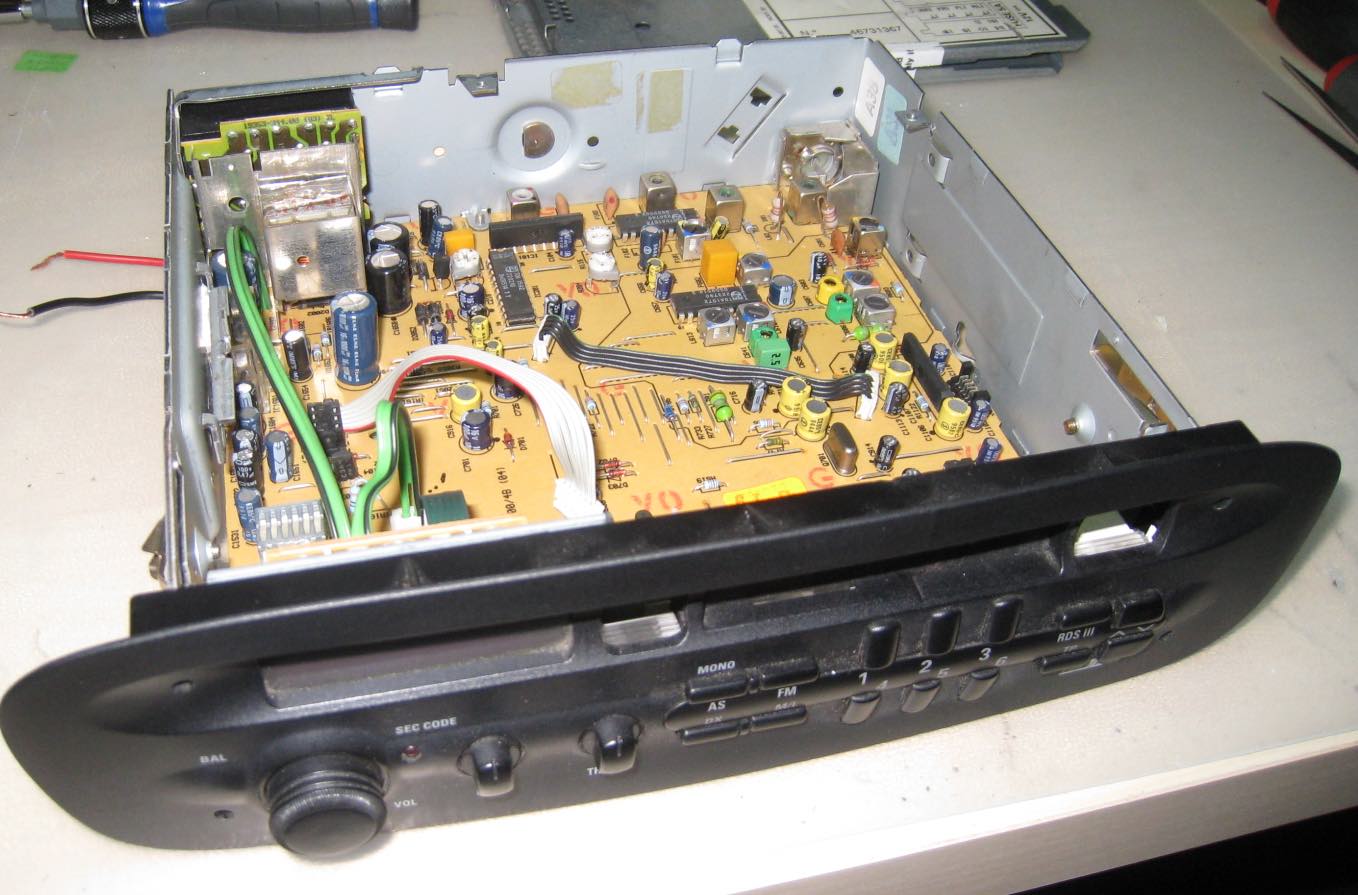
Opening the radio is very easy, using a small screwdriver to separate the cover from the body and rotating it (no screws). I removed both covers to see and understand everything, but actually it turns out that removing the bottom cover is enough if you want to read the memory in place, without desoldering it. Otherwise, if you want to remove the memory, you need to have the board accessible on both sides (and this means removing both covers and tape player mechanics… avoid it if you can…).
Now you need two things: a way to power the radio (12V DC) and a way to sniff IIC packets at switch-on.
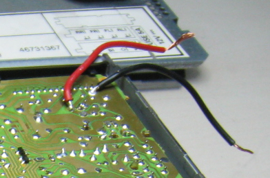
You can do this in many ways, but this is what I did. Looking at the schematic I found a couple of pads in the PCB where +12V and GND could be connected and soldered two pieces of wire (red and black), see picture. Then I used a benchtop power supply to provide power (12V, 0.5A) to the radio. I soldered two wires to clock and data of the IIC bus (see picture), to make them accessible with the probes of a digital oscilloscope (see picture).
Sniffing memory with a scope
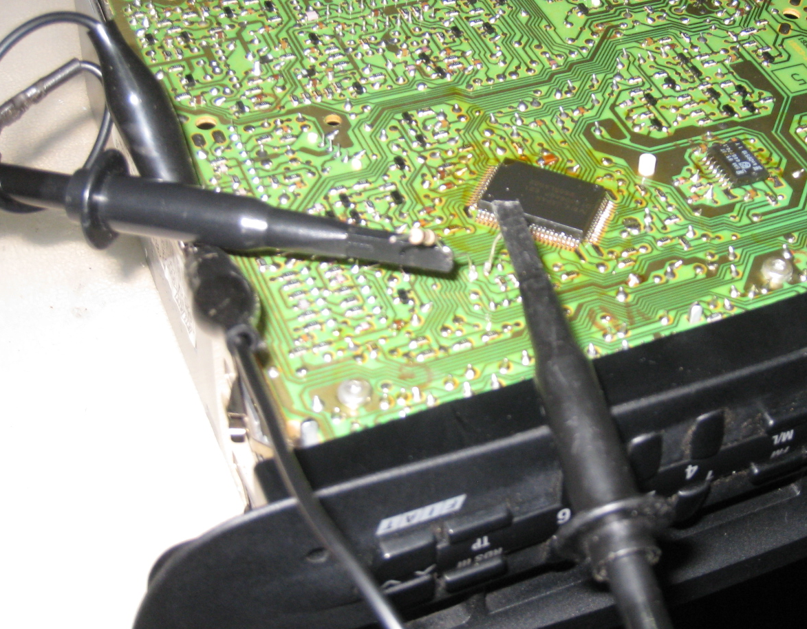
The tool I used is a two channel PicoScope. It’s a cheap digital oscilloscope that has nice features, among which the capability to decode IIC packets!!! I connected the probes to the clock and data pins of the radio PCB and configured the bus decoding feature and took some measurements.
As expected, at powerup the micro reads the memory. The good news is that it reads just a few bytes, so we can try to understand what happens. The bad one is that no one of the bytes read seem to have the right format to be the expected code, and we have no clue on what to do to find it.
| Sequence | Read location | Bytes read |
|---|---|---|
| 1 | 0x80 | 628A |
| 2 | 0x00 | 3E30 |
| 3 | 0x02 | 0A22 |
| 4 | 0xFC | 4659 |
| 5 | 0x02 | 0A22 |
| 6 | 0xFC | 4659 |
The code generator
Now it’s the time to take a look at GRUNDIG.EXE. First you need an old computer to run it. I was not able to run it in new computers, because it’s a 16-bit executable. I could run it using windows XP but it was not responsive. At the end I succeded using a DOS emulator, so I suppose an old computer running DOS should be fine, too.
Now let’s take a look at the input request of the program.
Type 4 HEX digits at adress #0 (for 93C46)
or at adress #1 then adress #0 (for 24C0X)
or at adress #11 then adress #10 (for 3000) =
We have to type two bytes (4 hex digits) depending on three options: the second seems the right one because 24C0X is a IIC memory similar to the one we have in the schematic, while 93C46 is not an IIC memory and 3000 is unknown to me. So let’s go with 24C0X.
From our previous measurements we suppose the four hex digits we have to type are: “303E”. (Note that it could have been also 3E30, for reasons related to endianness, not to be explained here… I have tried both and 303E was the one working properly.)
Let’s see the output.
Type 4 HEX digits at adress #0 (for 93C46)
or at adress #1 then adress #0 (for 24C0X)
or at adress #11 then adress #10 (for 3000) =303E
This Grundig CODE : 1014
3000 Grundig CODE : 3454
Safe 0 XOR 690F : 5931
Control XOR 1234 : 220A
Calculate next code? (Y/N)N
Two interesting things: 1014 could be our code and look, “control XOR 1234” has the same value that we read at address #2 (again, swapped for endianness). This makes me really confident we have the solution in hand!
Success!!
Now it’s time to input the code. Unfortunately, when you try too many times without success, the radio enters a long inactivity timeout, that after 6 tries is approximately of 24 hours. So I left the radio on (showing SAFE on the display) and the day after I found it ready for receiving the code (CODE on the display).
I entered the code as explained in the manual, pressed FM button for 3 seconds, and… guess it… everything worked!!!